// Engineering · Interactive Tool
Double-Wishbone
Suspension Geometry

Formula 1 cars use double-wishbone suspension at every corner. The geometry of the wishbone arms — their lengths, angles, and mounting positions — determines how the tyre behaves mid-corner: how much it tilts, how well it grips, and how the car's body rolls. Getting this geometry right is one of the most fundamental jobs in race car engineering.

This page walks through the theory from first principles, then lets you explore it interactively in the simulator below. If you already know the theory, skip straight to the tool.

Skip to simulator →
// 01
Camber Angle

Camber is the angle of the wheel relative to vertical, viewed from the front of the car. Zero camber means the wheel is perfectly upright. Negative camber means the top of the wheel tilts inward toward the car. Positive camber tilts it outward.

Camber angle diagram showing negative, zero and positive camber

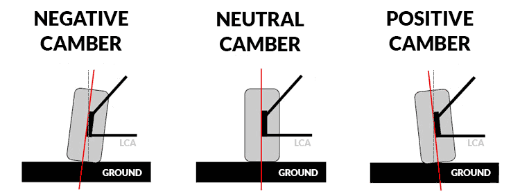
Negative, zero, and positive camber — viewed from the front of the car

When a car corners hard, the tyre deforms and its contact patch — the part touching the road — wants to peel away on one edge. A small amount of negative camber counteracts this, keeping more of the tyre flat on the road and maximising grip. F1 cars typically run −3° to −4° of static negative camber at the front because the cornering forces are so extreme.

The problem: as the suspension moves up and down, camber changes. A geometry that gives perfect camber when stationary might give terrible camber mid-corner. Designing how camber changes through suspension travel is the whole game.
// 02
The Double-Wishbone Layout

A double-wishbone suspension uses two A-shaped arms — upper and lower — connecting the wheel hub to the chassis. Each arm pivots at two points on the chassis side and meets the hub at a single ball joint on the wheel side. As the wheel moves up and down, both arms swing through arcs.

Labelled double wishbone suspension showing upper arm, lower arm, upright and chassis mounts

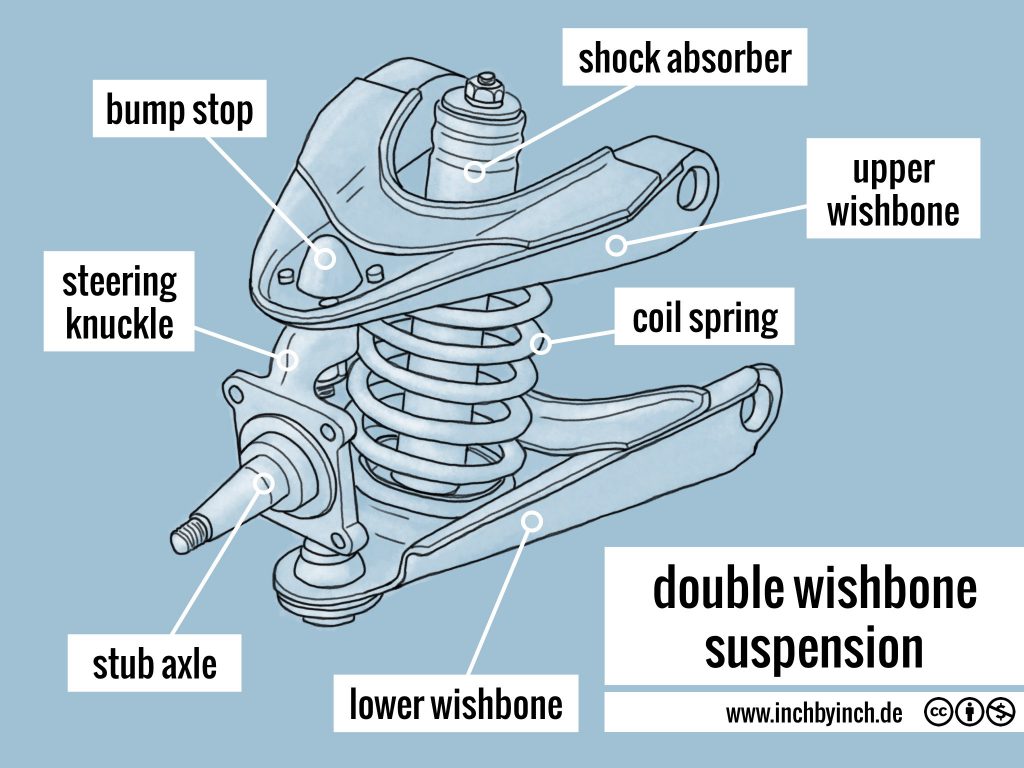
The double-wishbone layout — upper arm, lower arm, upright, and chassis mounting points

The critical detail: the upper arm is shorter than the lower arm. This is deliberate. If both arms were the same length, the wheel would move in a perfect parallelogram — staying perfectly vertical at all times. That sounds ideal, but in a corner the car rolls and the wheel simply tilts with the body, losing contact patch.

Because the upper arm is shorter, as the wheel compresses upward in a corner, the top of the wheel is pulled inward slightly faster than the bottom. The wheel gains negative camber automatically — fighting the roll and keeping the tyre flat on the road. This is built into the geometry passively, with no electronics or active components.

F1 uses double-wishbone at every corner because it gives engineers precise control over both camber change and roll centre height — something MacPherson struts, used in most road cars, cannot offer.
// 03
The Instant Centre

The two wishbone arms are at slightly different angles. If you extend a straight line through each arm outward away from the car, those two lines eventually meet at a point in space. That meeting point is called the instant centre.

Suspension diagram showing wishbone lines extended to meet at the instant centre

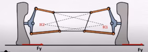
The instant centre — found by extending both wishbone lines until they intersect

At any given moment, the wheel assembly isn't just moving straight up and down — it's rotating about the instant centre. Think of it like the wheel is on an invisible arm, pivoting around that point. The instant centre is the tip of that invisible arm.

The instant centre moves as the suspension travels — hence instant, meaning it is only valid at that precise moment. The position of the instant centre determines the arc the wheel travels through and how aggressively camber changes. The closer the instant centre is to the wheel, the more aggressively camber changes in bump.

If the wishbones were parallel, the lines would never meet — the instant centre would be at infinity and the wheel would move in a perfectly straight vertical line. No camber change at all, and no ability to tune handling behaviour.

// 04
The Roll Centre

Once you have the instant centre, finding the roll centre is one more step. Draw a line from the instant centre down to the contact patch — the point where the tyre touches the ground. Where that line crosses the centreline of the car is the roll centre.

Diagram showing the line from instant centre to contact patch crossing the car centreline at the roll centre

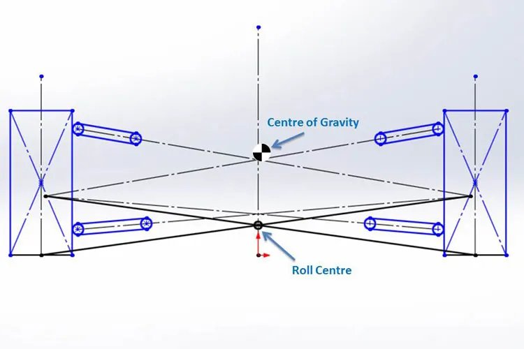
The roll centre — where the line from the instant centre to the contact patch crosses the car's centreline

The roll centre is the point around which the entire car body rotates when it rolls in a corner. Think of it as the pivot point of the car's lean. When the car corners hard, the lateral load acts through the centre of gravity — which sits above the roll centre. This creates a moment (a turning force) about the roll centre, rotating the body and compressing the outer suspension.

Higher roll centre → less body roll, but harsher lateral load transfer through the suspension. Lower roll centre → more body roll, but smoother and more progressive. F1 cars run the roll centre just a few centimetres above the ground for precise balance — and because it moves as the suspension compresses, it must be tuned across the full range of travel, not just at ride height.
// 05
The Mathematics

Every calculation in the simulator below comes from coordinate geometry — nothing beyond A-level maths. Each suspension component is represented as a point in 2D space (x, y), viewed from the front of the car. The origin sits at the contact patch on the car's centreline.

Step 1 — Define four pivot points as (x, y) coordinates:
Lower inner pivot: (x₁, y₁) — chassis side, lower arm
Lower outer pivot: (x₂, y₂) — wheel side, lower arm
Upper inner pivot: (x₃, y₃) — chassis side, upper arm
Upper outer pivot: (x₄, y₄) — wheel side, upper arm

Step 2 — Find line equations for each wishbone:
gradient m = (y₂ - y₁) / (x₂ - x₁)
intercept c = y₁ - m·x₁
→ y = mx + c (repeat for upper arm)

Step 3 — Solve simultaneously for the Instant Centre:
m₁x + c₁ = m₂x + c₂
x_IC = (c₂ - c₁) / (m₁ - m₂)
y_IC = m₁·x_IC + c₁

Step 4 — Find the Roll Centre:
Draw line from IC to contact patch (x_cp, 0)
Substitute x = 0 → y_RC = roll centre height

The camber angle is found from the geometry of the upright — the angle between the line connecting the lower outer pivot to the upper outer pivot, and the vertical. As bump travel changes, all four pivot positions shift, which means the instant centre moves, the roll centre moves, and the camber angle changes. The simulator recalculates all of this in real time.

// Interactive Tool
Suspension Geometry Simulator

Adjust the geometry using the sliders below. Every number updates in real time — try loading the F1 preset and dragging the wheel travel slider to see how camber and roll centre behave through a corner. Click the ? buttons for an explanation of any parameter.

Camber angle
-2.1deg
Camber angle is the tilt of the wheel relative to vertical, viewed from the front. Negative means the top leans inward. F1 cars run −3° to −4° to maximise tyre contact in corners. As you drag the bump slider, watch how camber changes — this is camber gain, the whole reason for using a double-wishbone over a simpler strut.
Most impacted by: upper arm length · upper mount height
Roll centre height
48mm
Roll centre height is the point the car's body pivots around when it leans in a corner. Think of it like a seesaw pivot — higher means less lean but harsher load through the suspension, lower means more lean but smoother. F1 runs it just a few centimetres above the ground. Learn how it's calculated: Roll Centre · Instant Centre.
Most impacted by: upper mount height · lower mount height
Instant centre dist.
840mm
Instant centre distance is how far the instant centre sits from the wheel. The wheel pivots around this point as it moves up and down. A closer instant centre means more aggressive camber change per mm of travel. A distant one (like F1) gives a gentler, more linear camber curve.
Most impacted by: arm lengths · arm angle (mount heights)
Wheel travel
0mm
Wheel travel shows how far the wheel has moved from its rest position. Positive (bump) means the wheel is compressed upward — exactly what happens to the outside wheel mid-corner as the car rolls. Negative (droop) is the inside wheel lifting away. All the other values update as this changes. See: why camber matters in bump.
This is the primary input — all other values respond to it
Wheel travel
Bump / Droop
0 mm
Drag right for bump (wheel compresses up — outside wheel in a corner). Drag left for droop (wheel drops — inside wheel in a corner). This is the most important slider — it shows the geometry changing in real time as the car corners. See: camber angle · roll centre.
Primary input — drives all geometry changes
Arm lengths
Upper arm length
200 mm
The upper wishbone is deliberately shorter than the lower arm. This length difference is what causes camber gain in bump. Shorter upper arm = more aggressive camber gain. Try shortening it and watch what happens to camber as you move the bump slider. F1 uses a very short upper arm relative to the lower for maximum camber control.
Directly controls camber gain rate · affects IC distance
Lower arm length
280 mm
The lower wishbone is the longer of the two arms, forming the main structural base of the suspension. A longer lower arm gives a wider, more stable geometry but reduces the difference from the upper arm — affecting how much camber is gained in bump. See: why arm length difference matters.
Affects camber gain, IC position, and geometry stability
Chassis mount heights
Upper mount height
280 mm
How high the upper wishbone mounts to the chassis, measured from the ground. This controls the angle of the upper arm, which has a large effect on where the instant centre sits and therefore where the roll centre falls. Raising this mount lifts the roll centre. Lowering it drops it.
Biggest single influence on roll centre height
Lower mount height
80 mm
How high the lower wishbone mounts to the chassis. Together with the upper mount height, this sets the angle of both arms relative to horizontal — the fundamental input that determines instant centre position and roll centre height. In F1, lower mounts are typically kept as low as possible for aerodynamic reasons.
Works with upper mount to set roll centre height
Camber curve vs wheel travel
Load preset: