This project takes the double-wishbone suspension geometry I modelled in the Suspension Geometry Simulator and pushes it into the third dimension — using Finite Element Analysis (FEA) in Autodesk Inventor to test whether a triangulated wishbone arm can survive realistic F1 cornering loads.
The analysis ran through five design iterations, each addressing a structural weakness found in the previous result. The goal was a geometry that produces a safety factor above 2.0 against the yield strength of 6061-T6 aluminium alloy — the material used in real racing suspension arms — under a 3,000 N lateral braking load.
The wishbone is fixed at both inboard pickup points — the pivots where it connects to the chassis — and loaded at the outboard hub connection, where cornering forces transfer from the wheel into the suspension. A 3,000 N lateral load was applied here, representing a realistic braking and cornering scenario for a small single-seater.
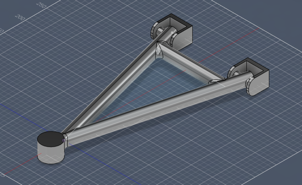
Initial wishbone geometry — isometric view in Autodesk Inventor
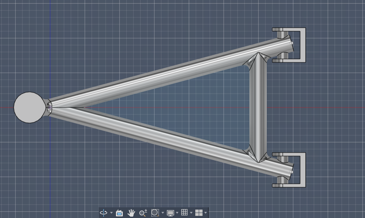
Top-down view showing the triangulated geometry and pickup points
The initial model used a simple solid triangular arm with no geometry optimisation. Under the 3,000 N load, the maximum Von Mises stress reached 506 MPa — nearly double the aluminium yield strength of 270 MPa. The stress concentrated heavily at the inboard pivot roots, which have the smallest cross-section relative to the bending moment applied there.
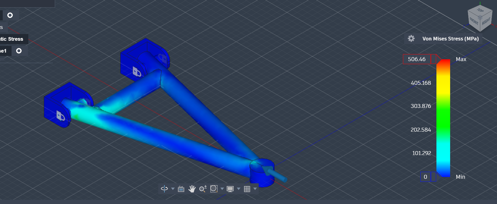
Von Mises stress distribution
Safety factor plot
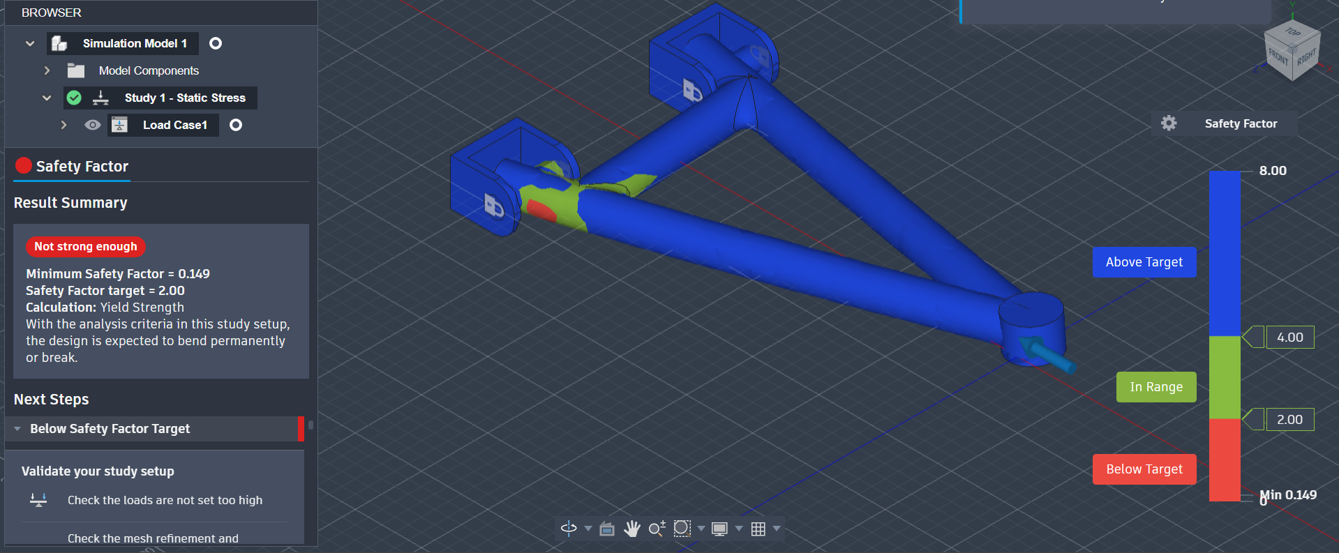
The safety factor of 0.53 confirmed the geometry would yield immediately in service. The key insight from this result was that material needed to be added at the inboard roots, not distributed uniformly across the arm.
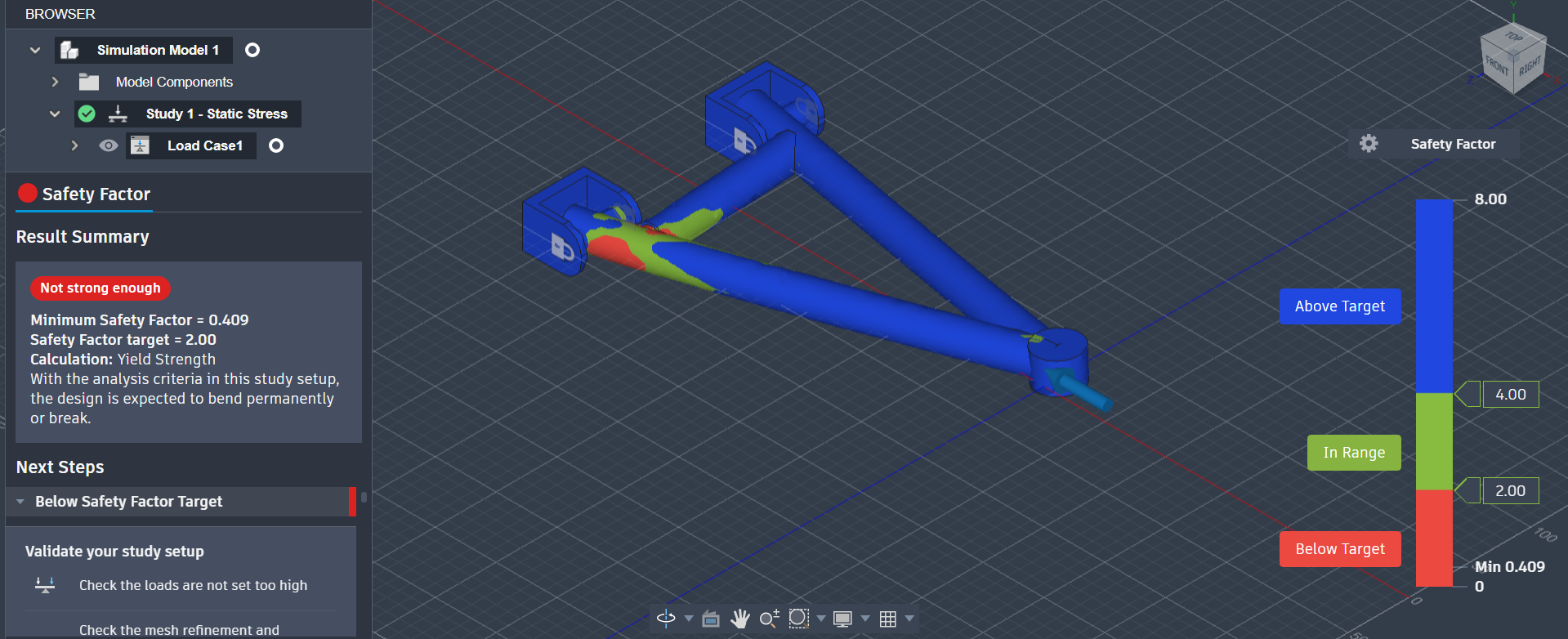
Generous fillets were added at all three pickup point roots to reduce the stress concentration factor. This brought the peak Von Mises stress down to 330 MPa — a meaningful improvement but still above the 270 MPa aluminium yield limit. The safety factor rose to 0.82.
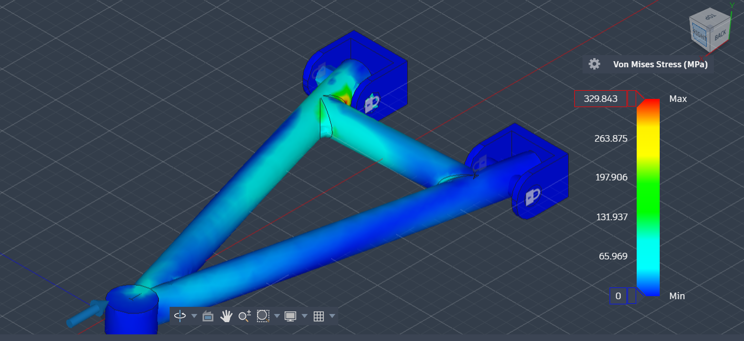
Von Mises stress distribution
Safety factor plot
The fillet approach had reached its limit — the arm cross-section itself needed rethinking. A solid flat plate was not an efficient structural form for this loading.
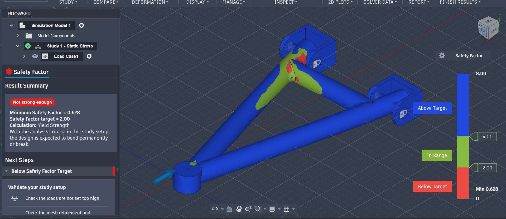
The arm was redesigned as a hollow tube structure to investigate whether a tubular section would distribute load more efficiently. The FEA returned a peak stress of 1,384 MPa — an implausibly high figure.
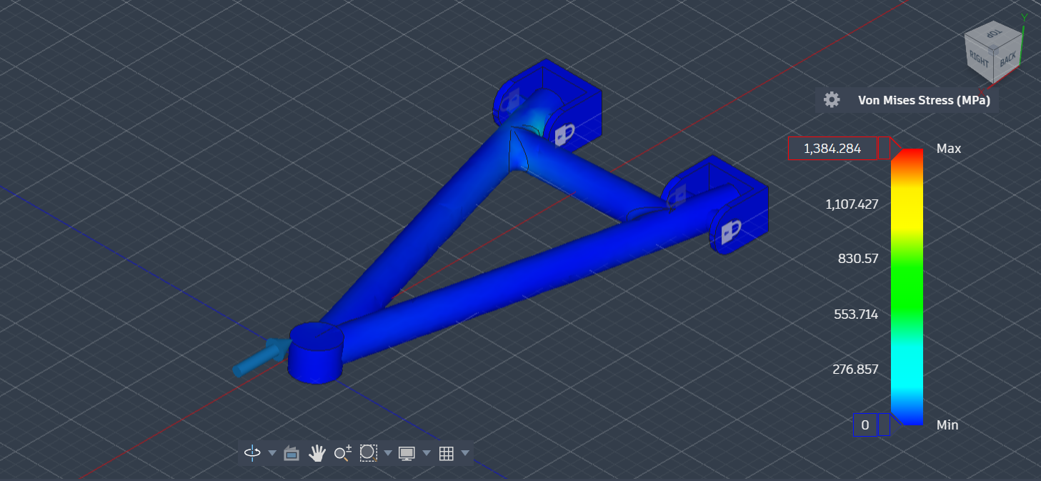
Von Mises stress — singularity visible at constraint point
Safety factor — artificially collapsed by singularity
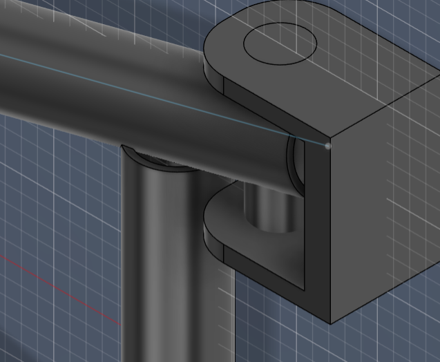
The problematic constraint configuration that caused the singularity
The hollow profile was replaced with a closed box section and the constraint method was corrected to apply reactions across a face rather than a point edge. Peak Von Mises stress dropped sharply to 116 MPa — well below the aluminium yield limit. Safety factor: 2.33.
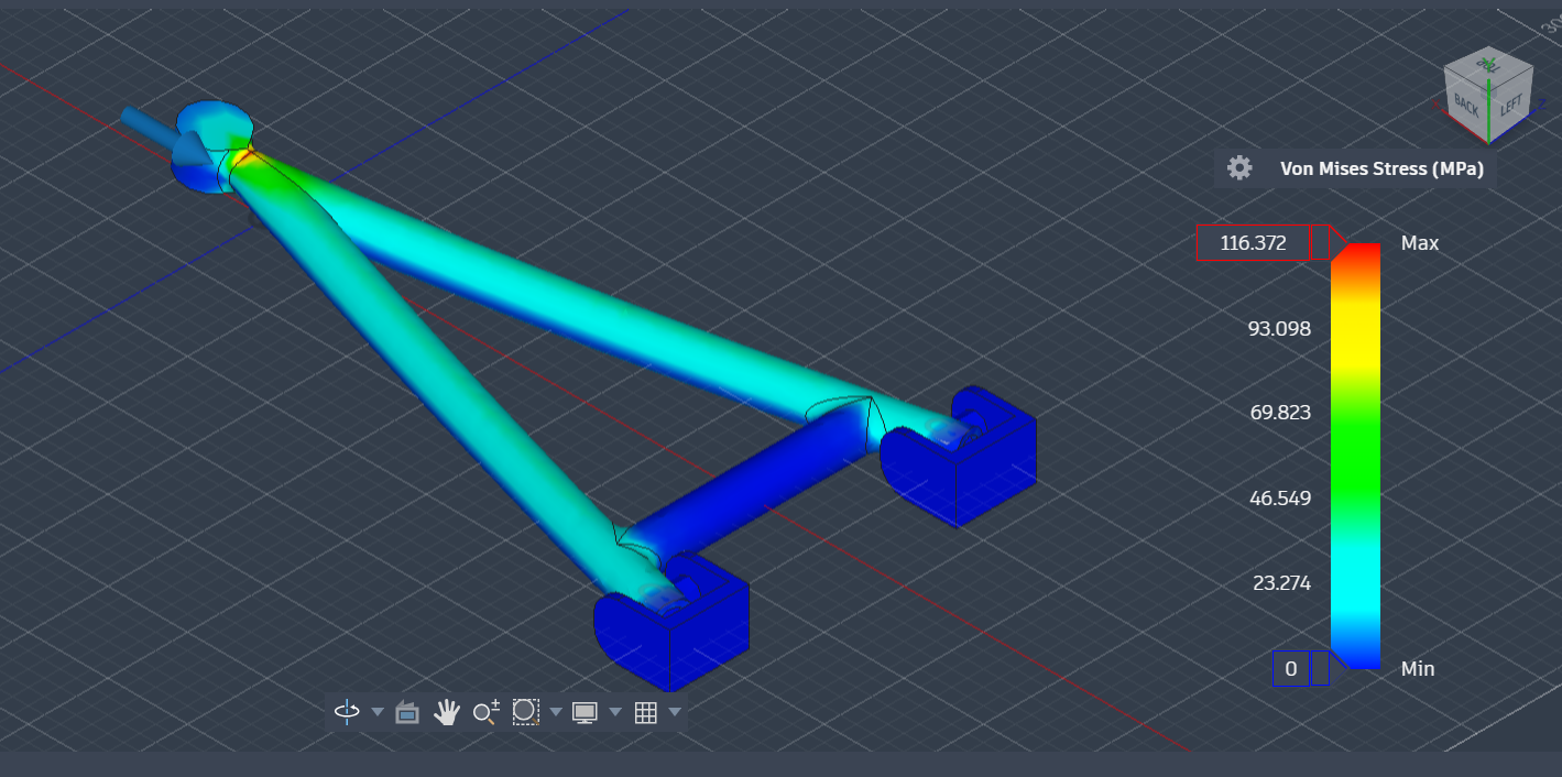
Von Mises stress distribution
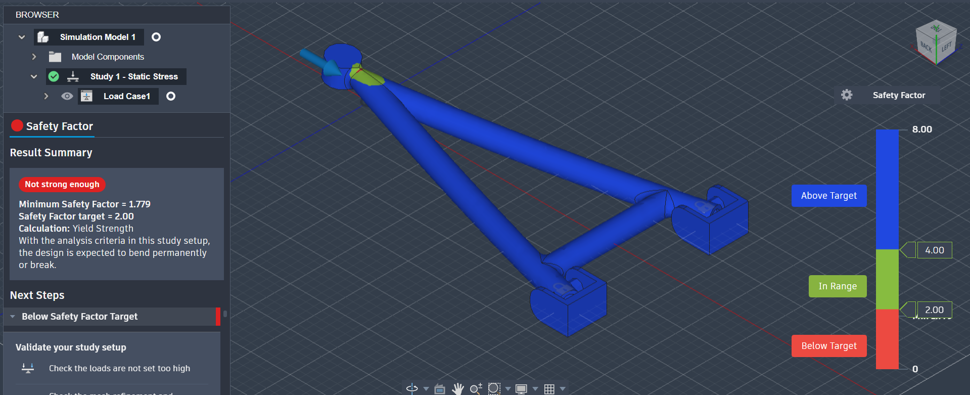
Safety factor plot — above 2.0 threshold
This was the first geometry to pass the 2.0 safety factor target. The box section provides significantly better second moment of area than a solid plate for the same material volume — the same principle behind I-beams and hollow structural sections in real engineering. With a SF of 2.33, there was still margin to refine further.
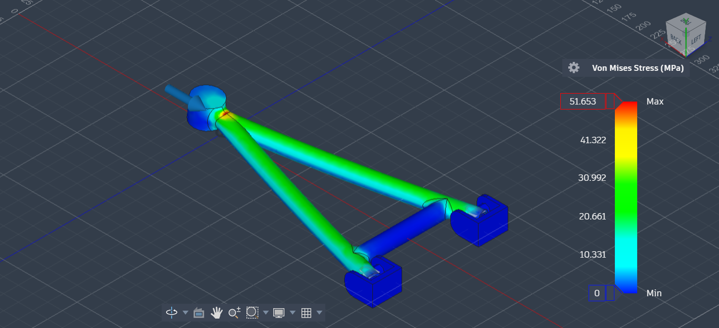
The final iteration refined the box section geometry — adjusting wall thickness and the triangulation angle to better align the arm with the principal stress directions. Peak Von Mises stress fell to 51.7 MPa, giving a safety factor of 5.22 against the aluminium yield limit.
Von Mises stress — final geometry
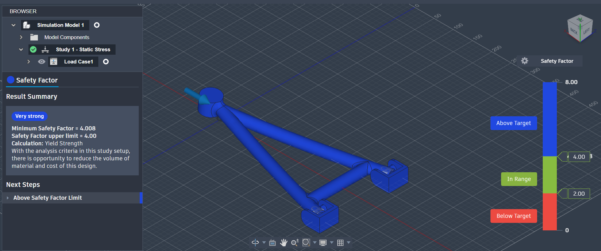
Safety factor plot — SF 5.22
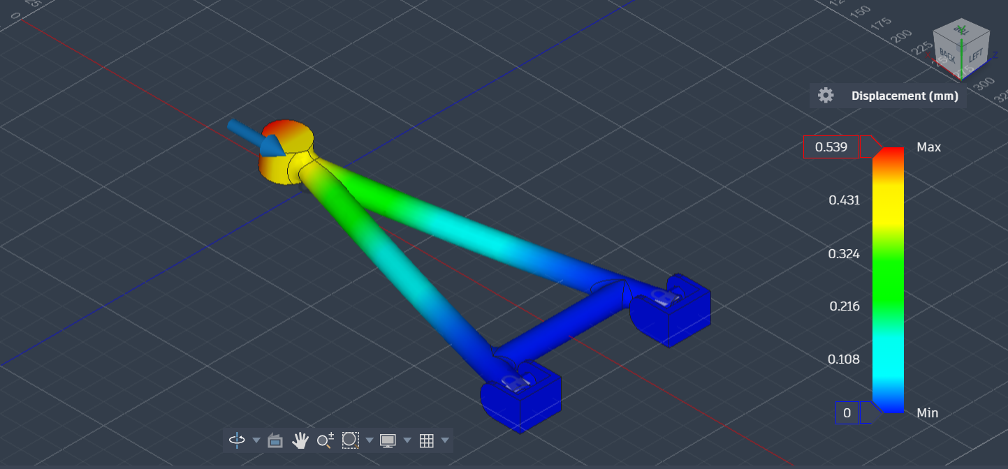
Displacement plot — final geometry under 3,000 N load
A safety factor of 5.22 is higher than strictly necessary — real F1 teams target factors closer to 2.0–3.0 because every gram saved matters at that level. But for a first FEA study the priority was understanding the methodology over minimum-weight optimisation. The displacement plot confirms the arm deforms predictably under load, with maximum displacement at the outboard hub — exactly where the geometry is least constrained.
The table below summarises all five iterations. Von Mises stress values come directly from the FEA output and are material-independent. Safety factors are calculated against the 6061-T6 aluminium yield strength of 270 MPa.
| Version | Change Made | Max Stress (MPa) | Safety Factor | Result |
|---|---|---|---|---|
| V1 | Baseline solid arm | 506 | 0.53 | Fail |
| V2 | Root fillets added | 330 | 0.82 | Fail |
| V3 | Hollow tube profile | 1,384* | — | Singularity |
| V4 | Box section + corrected constraints | 116 | 2.33 | Pass |
| V5 | Refined wall thickness + triangulation | 51.7 | 5.22 | Pass |
* V3 stress value reflects a mesh singularity artefact, not a real structural result.
This was my first time using FEA software independently, and the process taught me as much about the limitations of simulation as it did about structural engineering. The V3 singularity result was initially confusing — a 1,384 MPa stress figure that made no physical sense. Diagnosing it correctly required understanding how FEA solvers distribute constraint reactions and why point constraints on thin-walled features cause numerical instability.
The bigger lesson was about the relationship between cross-section geometry and structural efficiency. The solid plate in V1 and V2 used more material than the box section in V4 but performed far worse — because the second moment of area, not the total cross-sectional area, determines bending stiffness. This is the same reason that structural steel comes in I-beam or hollow rectangular profiles rather than solid bars.
Understanding why real teams use aluminium alloys rather than steel also came into focus here: aluminium's yield strength per unit mass is higher than mild steel's, and in suspension components where unsprung mass directly affects dynamic performance, that trade-off is critical. The FEA gave me a quantitative basis for a design decision I previously understood only qualitatively.